
|
The Microscope Lamp.
Design Considerations for the Ideal Köhler Illuminator. |
Page 3 of 5 |
|
|
The Microscope Lamp.
Design Considerations for the Ideal Köhler Illuminator. |
Page 3 of 5 |
The lamp shown here achieves many of the objectives outlined on the previous pages. The condenser is of wide aperture and large diameter, and is easily removed and dismantled for cleaning. Three light sources -- filament lamp, optical light guide and white LED -- are easily exchanged, condenser and source elements are independently focusable, and the filters are held sufficiently far in front of the condenser for dust to be out of focus. 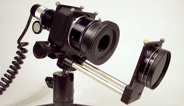
Assembled microscope lamp with tungsten filament source. The picture of the dismantled lamp (below) shows the basic structural unit to be a 35mm photographic bellows (made by BPM -- alas no longer in business) with two independently racking elements joined by a light-tight fabric bellows, and each element with a clamping circular dovetail fitting which accepts adapter rings to which the condenser, lamp housing and filter modules are screwed. 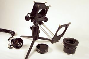
The bellows unit is attatched to a photographic ball and socket head which has provision for independent 360° pan and which can be separately clamped, and the whole is attatched to a small, strong folding table tripod, made by Manfrotto. The tungsten filament lamp is fitted into a bayonet socket from a Russian microscope lamp, which happens to be a neat sliding fit in a short length of standard microscope eyepiece tube which is clamped in a BPM microscope adapter. The filters are standard Nikon 52mm screw mount, allowing as many filters as required to be threaded together. These filter mounts accept lenses and filters of 50mm diameter -- a common standard size. The condenser unit is also composed of standard Nikon 52mm extension rings and filter mounts, and the iris diaphragm, from an optical catalogue, is attatched by means of a step-up filter adapter of the kind supplied by most photographic retailers. The requirements of large diameter, wide aperture, short focal length and a high degree of spherical correction in a condenser can only be met in any practical sense by the use of aspheric lenses. Since aspheric condenser lenses are corrected for spherical aberration at infinite conjugates (source at principal focus, emergent rays parallel), a field lens must be used in combination with the aspheric element to bring the rays to a focus at the required distance from the lamp. Since the required distance is 250mm, a plano-convex lens of 250mm focal length is used with its convex surface facing the aspheric element. A best-form lens of this focal length would be ideal, but plano-convex lenses are more easily obtained and do a similar job. 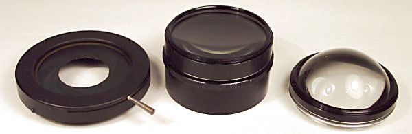
Lamp condenser components. The aspheric used in this case has a diameter of 50mm, a focal length of 35mm. and an aperture of f 0.7, the combination with field lens producing an image of the source remarkably free of spherical (though not chromatic) aberration. The compromise here is that 35mm is not quite short enough a focal length to project a large enough filament image into the microscope substage at 250mm -- the lamp must be moved further from the microscope. This is however, not a problem when a fibre optic light guide is used as source -- see later. 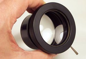
A point to remember is that the illuminated background to the specimen in Köhler brightfield is not the source itself, but the lamp condenser filled with light from the source. The evenness of this background is critically dependent on the uniformity of the source, the optical correction of the lamp condenser, the alignment of the lamp, and to a lesser extent, the quality of the microscope substage condenser. If the lamp condenser cannot be filled with an even light, there is no chance of achieving even illumination of the field at the plane of the specimen without the use of diffusers or defocus of the substage condenser. Since Köhler illumination requires that the condenser lens filled with light be re-imaged in the plane of the specimen, the problem arises as to how such a featureless entity can be be bought to a visible focus. The edges of the lamp diaphragm blades are used to define this plane, which is why, in order to minimize the small error involved, the lamp diaphragm must be as close to the condenser lenses as possible -- point 5 on the previous page. (In fact, the diaphragm should be placed at the exit pupil of the condenser lens, which is usually somewhere within the thickness of the lens combination, but to go to this trouble really would be splitting hairs to no discernible benefit). The most common source in use today is the tungsten filament lamp, and there are inherent problems associated with obtaining an even fill with this source, due 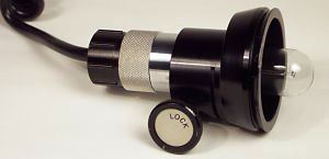 to the nature of the filament. The reader is therefore referred to these
pictures of filament types from the article on flash photomicrography.
to the nature of the filament. The reader is therefore referred to these
pictures of filament types from the article on flash photomicrography.
The tightly wound grid structure and larger size of the Olympus lamp filament represents the best type in terms of ease of achieving an even fill of light, and the Russian filament type (and even more loosely wound filaments) represent the most difficult, especially for the lowest power objectives, which require the largest area of lamp condenser to fill their fields. The problems stem from the non-uniformity of the source -- between the "bars" of the filament, there is no light at all. In those lamp housings which use a concave spherical mirror with a tungsten-halogen lamp at its centre, the mirror can be adjusted so that the reflection fills (as far as possible) the spaces between the actual filament bars, giving a much improved source uniformity. Another approach is to use the inverted mirror image to double the apparent source size (in the case of the narrower tungsten-halogen filaments) simultaneously placing the non-uniformities on a smaller scale. With the end-on bulbs used in the present lamp design, the use of a mirror is not an option. Change in effective size with intensity (Point 7, previous page) is another problem encountered with tungsten filament lamps. Here is a link to pictures showing the way in which the unavoidable cooling of the outer parts of the filament effectively reduces source size at the low lamp currents often required for the lowest powers. The problem is largely overcome by using the lamp at a higher current and reducing its intensity with neutral density filters. A difficulty with this particular lamp when used with a tungsten bulb is that the lamp housing has no centreing provision. However, centration is fairly good if the lamp itself is symmetrically constructed and the bayonet socket allows clamping of the lamp base. Also, there is no ventilation, and the bellows grow uncomfortably hot when the lamp is used at full intensity. If tungsten lamps are intended to be the main source of illumination, the bellows should be removed and a blackened thin metal baffle constructed which could be placed over the lamp to block stray light. However, these problems go away when a fibre light-guide is used as the light source. This was the main intention of the design, and is discussed in detail next.
|