 The Two-Lens Abbe Condenser.
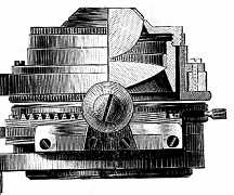
 The cross-section diagram (right) is of an Abbe condenser of one hundred and twenty years ago. Except for minor mechanical details, this diagram describes the condenser routinely fitted to laboratory microscopes today.
Microscopes usually leave the factory with the substage condenser adjusted so that the closest approach to the specimen brings the toplens surface to within a whisker of the stage surface. With a specimen on a slide of normal thickness (c. 1.2mm) the condenser will still focus the lamp diaphragm in the plane of the specimen, but with the toplens safely below stage level. This makes it impossible to scratch the condenser toplens with the slide.
In practice, most condensers achieve their focus with something less than 1mm between the toplens and the slide. It is then feasible to immerse them to the under-surface of the slide with oil (or water) to achieve a larger illumination aperture, better spherical correction and increased light throughput.
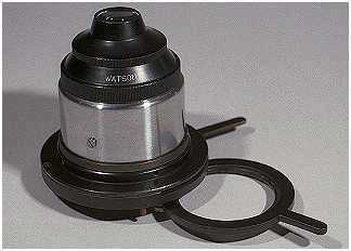
 The illustration (left) is of a Watson two-lens Abbe substage condenser of c.1950, and is typical of condensers of its kind. The strongly curved top-lens can be removed to give a lower power condenser which is better suited to illuminating the field of low power objectives.
The stop carrier is used for holding light filters and diffusers, and for holding and positioning darkfield stops. The use of diffusers cannot be recommended except as a last resort in an attempt to obtain an evenly illuminated field. The penalty for using them is loss of control of the illuminated field in the specimen plane (with associated flare and contrast loss) as the lamp diaphragm cannot be seen or focused. A diffuser will also severely reduce the intensity of the illumination.
If light intensity control is not possible at the lamp, it is best achieved by placing neutral density filters in this carrier.