 |
Using the Microscope.
Introductory Tutorial. Component Parts of the Microscope. |
Part 2 of 9 Page 1 of 1 |
|
Using the Microscope.
Introductory Tutorial. Component Parts of the Microscope. |
Part 2 of 9 Page 1 of 1 |
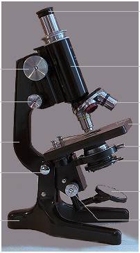
The Watson "Service" microscope shown here is of a general design developed in the early 1900s, and microscopes of this type are still in wide use. It is a simple, rugged, well-made instrument of a kind that, with proper care, will still be functional after hundreds of years of frequent to occasional use. Additionally, it has a drawtube -- the collar seen between the eyepiece and the body tube -- which makes it possible to alter the mechanical and optical tubelength of the instrument. The use of this refinement will be covered in the advanced tutorials.
The optical components are those of all compound microscopes, and even though this model has no integral lamp, this discussion will begin with the lamp, and proceed in sequence via the mirror to the eye.
 Microscopes require, especially at the highest powers, intense
illumination. The intensity of a light source depends not so much upon its absolute power
as upon the amount of light emitted from a given area of the source -- lumens
Microscopes require, especially at the highest powers, intense
illumination. The intensity of a light source depends not so much upon its absolute power
as upon the amount of light emitted from a given area of the source -- lumensThe combination of a suitable quartz-halogen bulb with a concave spherical reflector works well and is also in wide use. For more detail on lamp issues: The mirror is used only to fold the optical path of the microscope into a convenient space. It also introduces another source of potential maladjustment into the system, and another surface to collect dust. Having said this, the mirror does not need to be of the highest optical quality to do its job, nor does a small amount of dust on the mirror make much difference to the quality of the image. A slight film of fine dust (such as remains after dusting the mirror with a blower brush) can actually be useful in locating the beam of light from the lamp when setting up the instrument. Always use the flat side of the mirror in combination with a substage condenser.  The substage condenser fitted to most microscopes is of a design originated by Ernst Abbe in the late 1800s and is usually referred to as the Abbe condenser. Whilst condensers of higher correction are available, the Abbe condenser has proven to be quite satisfactory for routine microscopy.
A substage condenser of some kind is an absolute requirement for serious -- or at least satisfactory -- microscopy. The objectives from x20 upwards require the subject to be illuminated evenly over quite a large angle, and neither a concave mirror nor (especially) a flat mirror is capable of achieving this. If no condenser is used with a high power objective, the result is an image which is dark, coarse, contrasty and lacking in detail -- described by earlier microscopists as "a rotten image". Lower power objectives however, can give acceptable, even quite pleasing images without a condenser if the mirror is directed toward a close, well frosted lightbulb or a bright white cloud. An important point to note here is that the substage condenser diaphragm is used to control the solid angle of the light emerging from the condenser, illuminating the specimen, and filling the objective -- not for adjusting the brightness of the image. Brightness adjustment can be achieved by removing or placing a filter in the substage stop-carrier or by dimming the lightbulb, locating a brighter or a greyer cloud etc. In practice, once the microscope has been set up, the condenser and its diaphragm setting can be largely forgotten until the objective is changed for one of higher or lower power. More Information on Condensers. Most substage condensers are corrected to work with a slide thickness of 1.0mm, and most microscope objectives of x20 or greater power are designed to work with a coverglass thickness of 0.17mm (thickness no. 1½).  The objective is the most important component of the optical system in terms of the quality of the final image. For over a hundred years, dating from Ernst Abbe's introduction (in the 1870's) of apochromatic corrections, the best objectives have been capable of resolving the finest detail predicted by theory. Since then, great improvements have been made in field size, field flatness and image quality toward the edges of the field. The modern microscope objective probably represents the highest degree of optical perfection and precision engineering which is manufactured in volume for public consumption. The diagram shows a construction (not to scale) typical of a x40 achromatic objective standard on most laboratory microscopes.
The screw thread of microscope objectives has been a standard across the industry since 1858, when it was first proposed by the Royal Microscopical Society. Here is a diagram of the RMS standard objective thread. More recently, larger diameter threads have appeared to accommodate the needs of modern objective design. More Information on Objectives.  The eyepiece relays to the eye an image projected by the objective into the plane of the eyepiece diaphragm, further magnifying it in the process. In older microscopes, the eyepiece also corrected residual colour errors remaining in the objective. Modern infinity-tubelength objectives are fully corrected in themselves, but still require additional focusing optics and appropriate eyepieces to produce their image. The matching of older objectives to a suitable eyepiece is also discussed in the advanced tutorials.
In short, all objectives manufactured before the arrival of infinity-correction required "compensation" of varying degrees. There was no industry-wide standard on the matter, so each manufacturer produced eyepieces which compensated the lateral colour errors of their own objectives. The degree of compensation of a compensating eyepiece can be roughly gauged by the intensity of the red fringe seen inside the eyepiece diaphragm when used on brightfield. The brighter the fringe, the greater the degree of compensation. All of the apochromatic objectives of this (almost hundred year) period, and many of the higher power achromats, required compensating eyepieces. The other variety of eyepiece in common use was the Huyghenian -- best suited to achromatic objectives in general, and particularly to low power achromats which often require little or no correction. These eyepieces are distinguished by a blue fringe around their field diaphragm when the eyepiece is used in brightfield.  The cornea and the eye lens are the final optical components in the image-forming path to the retina. In a person with normal vision, the eyelens will be relaxed as though the eye is forming an image of a very distant object, and the focusing controls on the microscope used to achieve image sharpness. The optics of the eyepiece are such that all image-forming rays pass through a circle (called the Ramsden disc) a few millimetres exterior to the eyepiece lens and just smaller than the diameter of the pupil. The eye is bought close enough to the eyepiece for the ramsden disc and the pupil to coincide, at which point the full circular field of the microscope is seen.
Learning to hold the head still in this optimum position, especially with a binocular instrument, is one of many skills acquired by the microscopist. Click for a diagram of the human eye. Having briefly covered the components of the microscope and their function, the next step is to refer to diagrams of the Köhler setup to see the optical relationship between the components prior to the setup procedure itself.
|